


All Products
-
 rhode alain,FranceIt is very nice to work with real professionals. They are attentive and responsive.
 -
 Alejandro Gidi,Mexicoexcellent communication from seller. Ms Daisy was clear and on time, product was shipped properly packaged. A+
 -
 Sergey Shapotkin,Russian Federeverything fine
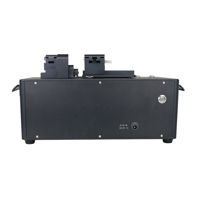
Large-Diameter Fiber Cleaver Cleaves Silica Glass Fibers with Cladding Diameters from Ø60µm to Ø600µm


Product Details
| Cleave Type | Flat Cleave | Accepted Fiber Sizes | Cladding: Ø60µm To Ø600μm Buffer: Ø105µm To Ø1000μm |
|---|---|---|---|
| Accepted Fiber Types | Quartz/Glass Single Fiber, SM, PM, MM, Etc. Specialty Fibers | Cleave Method | Tension And Scribe |
| Tension | 0~53.7 N (Max., Programmable*) | Tension Accuracy Control | 0.01kgf |
| Scribe / Blade Life | Diamond Blade, Stepper Motor Controlled (5000 Uses, 10 Positions) 50,000 Scribe Life (@ Cladding Diameter 125μm) | Loading | Linear Tension, Stepper Motor Controlled |
| Cleave Tolerance | ±1.0° (Typ. 90°±0.5°) | Cleave Length | 5~25mm |
| Fiber Holder Inserts | Available Separately | Number Of Cleaving Modes | 5 Stored Program Modes (Default, Max.), Support Self-configuration |
| Language | English/Chinese | Monitor | 3.5 Inches Color LCD, Touch Screen |
| Power | 12 VDC, 2 A (Provided By External Power Supply) | External Power Supply | 100 - 240 VAC, 1.6A, 50/60 Hz |
Product Description
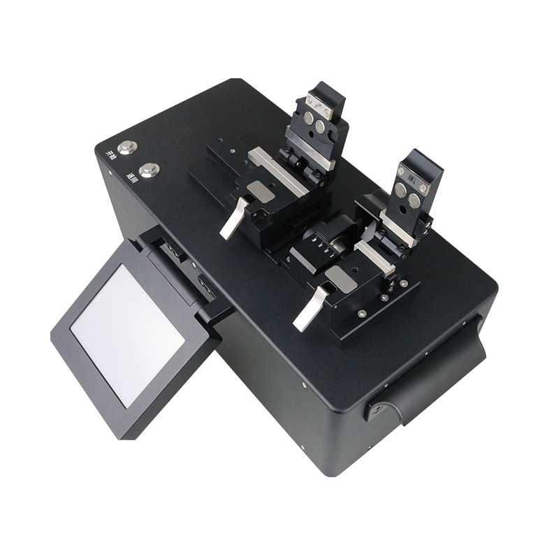
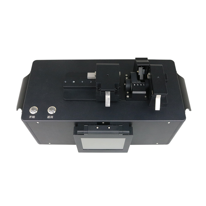
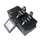
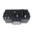
Large-Diameter Fiber Cleaver
Cleaves Silica Glass Fibers
with Cladding Diameters from Ø60µm to Ø600µm
Model No.: LDC9901
Auto & Precision & Durable
Description
These Compact Automated Large-Diameter Fiber Cleavers are designed for cleaving fibers with claddings from Ø60μm to Ø600μm with a high degree of accuracy, ease of use, and versatility in manufacturing or research environments. The LDC9901 is designed to produce flat cleaves perpendicular to the length of the fiber.
Each unit operates with a tension-and-scribe cleave method, whereby axial tension is first applied to the fiber followed by an automated scribe process utilizing a diamond cleave blade. After the blade scribes the fiber, tension is maintained, causing the scribe to propagate across the fiber perimeter and complete the cleave. The resulting cleave will be perpendicular to the maximum resultant stress created by the tension applied to the fiber. This method produces consistent low-angle cleaves with mirror-quality end-face finishes, ideal for splicing, and has a cleave angle accuracy of ±1.0° (Typ. 90°±0.5°).
Cleaving parameters can be configured and controlled from a built-in touch screen interface. All that is needed to know is the cladding & buffer coating of the fiber you want to cut. For more details about the software configuration, please read the user manual carefully or contact the technical assistant.
Each cleaver includes a diamond blade for scribing the fiber. When used with proper cleave parameters, a single location on the blade can provide up to 5,000 cleaves (dependent on the cladding properties of the fiber being cleaved). The cleaver is designed so that the cleave blade can be repositioned approximately 10 times before replacement (assuming proper cleave parameters and usage that does not cause unexpected damage to the blade). For more information, please refer to the cleaver manual, replacement cleave blades are available.
Software Define Processing
The LDC9901 software includes parameters that allow for high-quality cleaves of large-diameter specialty fiber. This software define process applies a tension that is lower than required for a "standard" cleave. The blade then scribes the fiber while the tension is being incrementally increased to propagate the scribe and produce a cleave. Since the resulting crack is allowed to propagate relatively slowly with little driving force, a smoother cleave result.
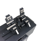
Inserts (Required and available separately) used in the Left and Right Fiber Holding Block
Fiber Inserts, available separately, are required for loading the fiber into the LDC9901 Fiber Cleaver. These Inserts should be selected based on the fiber buffer coating or cladding diameters.
When the inserts are loaded into the fiber holding block, the mounted fiber will lay across a left fiber holding block that will anchor the useful portion of the fiber during the cleaving process, while the unmounted fiber will lay across a right fiber holding block that will anchor the discarded or "waste" portion. These holding blocks contain a top and bottom insert, sold separately, with V-grooves designed to retain specific fiber buffer coating or cladding diameters. Aluminum alloy block and stainless-steel setscrews are used to secure the inserts in the fiber holding blocks
Features
- Flat (0°) of Ø60μm to Ø600μm Cladding Fiber
- Programs for Cleaving Standard or Specialty Fiber
- Left V-Groove Fiber Inserts for Loading Fiber into the Cleaver (Required and Sold Separately), Accepts Fiber with Ø105μm to Ø1000μm Buffer or Ø60μm to Ø600μm Cladding
- Right V-Groove Inserts Hold Discarded Fiber End (Required and Sold Separately), Accepts Fiber with Ø60μm to Ø600μm Cladding
- Mirror-Quality End-Face Finishes Critical for High-Performance Splicing
- Location-Specific Power Cord Included
Specifications
| Model No. | LDC9901 |
| Cleave Type | Flat Cleave |
| Accepted Fiber Sizes | Cladding: Ø60µm to Ø600μm Buffer: Ø105µm to Ø1000μm |
| Accepted Fiber Types | Quartz/Glass Single Fiber, SM, PM, MM, etc. Specialty Fibers |
| Cleave Method | Tension and Scribe |
| Tension | 0~53.7 N (Max., Programmable*) |
| Tension Accuracy Control | 0.01kgf |
| Scribe / Blade Life |
Diamond Blade, Stepper Motor Controlled 50,000 scribe life (@ Cladding diameter 125μm) |
| Loading | Linear Tension, Stepper Motor Controlled |
| Cleave Tolerance | ±1.0° (Typ. 90°±0.5°) |
| Cleave Length | 5~25mm |
| Rotation Stage | N/A |
| Fiber Holding Blocks |
Internal Magnetism for Easier Insert Loading, Manual clamping with torque driver when required |
| Fiber Holder Inserts | Available Separately |
| Number of Cleaving Modes | 5 stored program modes (Default, Max.), Support Self-configuration |
| Language | English/Chinese |
| Monitor | 3.5 inches Color LCD, touch screen |
| Power | 12 VDC, 2 A (Provided by External Power Supply) |
| External Power Supply | 100 - 240 VAC, 1.6A, 50/60 Hz |
| Dimensions (W x D x H) | 305(W) x 150(D)x 153(H) mm |
| Weight | 10.0 lbs (4.5 kg) |
| Operation condition | 0 to 95% RH and 0 to 40°C (non-dew) |
| Storage condition | 0 to 95% RH and -40 to 80°C (non-dew) |
Note:
*These cleavers are calibrated using standard weights that are hung off of a pulley, so the tension settings are programmed into the tablet controller in grams. This maximum tension corresponds to 5.5 kg.
Order Information
1. Fiber Type
2. Cladding Diameter
3. Coating Diameter
4. Fiber Holder Inserts Selection
| Part # | Model No. | Description |
| 31210 | LDC9901 |
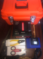
1 PCS Large Diameter Fiber Cleaver 1 PCS 12 VDC External Power Supply Adapter w/ Location-Specific Power Cord 1 PCS Nylon Cleaning Brush 1 Set Inserts (Included Two Required Fiber Holder Top Inserts, Two Required Fiber Holder Bottom Inserts), Size as requested 1 PCS Carrying Case 1 PCS User Manual |
Sample: Fiber Holder Inserts Selection for Specialty Fiber, MM, Cladding/Coating Diameter: 400/550μm
| Part # | Model No. | Description |
| 31227 | LTi-550 | Fiber Holder Left Top Insert, Ø550μm |
| 31234 | LBi-550 | Fiber Holder Left Bottom Insert, Ø550μm |
| 31241 | RTi-400 | Fiber Holder Right Top Insert, Ø400μm |
| 31258 | RBi-400 | Fiber Holder Right Bottom Insert, Ø400μm |
Accessories
| Part# | Model No. | Description | Remarks |
| 31265 | RB-9901 | Replacement Diamond Cleave Blade for LDC9901 |
Inserts in Store*
|
LTi-550 LBi-550 |
RTi-400 RBi-400 |
|
LTi-330 LBi-330 |
RTi-220 RBi-220 |
|
LTi-135 LBi-135 |
RTi-80 RBi-80 |
|
LTi-105 LBi-105 |
RTi-60 RBi-60 |
*Custom Inserts Available.
![]()
Adjustable Stop Attachment - Optional
| Model No. | Description | Remarks |
| AS-9901 | Adjustable Stop for LDC9901 |
Reference Guide*
![]()
Note:
*All diameter of fiber holder inserts can be customized, please contact our technical assistant for details.
![]()
Each V-groove can accommodate a range of fiber sizes
![]()
Introduction
Fiber Holder Inserts, which are designed to hold various-sized fibers within the cleaver, must be purchased separately. The bottom inserts have V-grooves to hold the fiber, while the top inserts each feature a flat surface that clamps the fiber against the V-groove in the bottom insert. Each top and the bottom insert is sold individually, as the fiber diameter clamped by the left and right holding blocks may not be the same. Two top inserts and two bottom inserts are required to operate the cleaver.
The table above indicates the maximum and minimum diameters that can be accommodated by different combinations of top and bottom inserts. It also indicates how far offset the fiber will be for recommended combinations of top and bottom inserts. Note that the fiber outer diameter may be the fiber cladding, jacket, or buffer. If one side of the fiber is being discarded, it is preferable to clamp onto the cladding of this section except in special cases where the coating or buffer may be preferable. Sections of fiber that are not being discarded should always be clamped on the coating or buffer in order to avoid damaging the glass. This may require different sets of fiber holder inserts to be used in the left and right holding blocks. In this case, it is important to minimize the difference in the offsets introduced by the left and right sets of inserts when attempting to produce perpendicular, flat cleaves.
Fiber Holder Insert Selection Chart
1. First, select the bottom insert that matches your fiber size most closely.
Example: For an Ø800 µm fiber, the Bi-750 insert is the closest match, since it is only 50 µm smaller.
2. On the chart, look to the right of your chosen bottom insert. Select a compatible top insert based on the fiber diameter size range shown in each cell.
Example: For the Ø800 µm example fiber from step 1, the green cell is in the 750 µm groove column for the Ti-750 top insert. The numbers listed in the green cell indicate that this combination of inserts is good for fibers from 728 to 963 µm in diameter. Our Ø800 µm fiber is within this range, so this is a good choice. There are several other options as well that will accommodate an Ø800 µm fiber as well, but the green shading in the chart indicates that the 750 µm groove in the Ti-750 provides the best fit.
3. The second line of numbers in each cell shows the range of offsets that can be expected for any given combination of top and bottom inserts. When selecting inserts for the right and left fiber holding blocks, try to minimize the offsets between the pairs of inserts on each side.
Example: If we choose a Bi-750 bottom insert and the Ti-750 top insert, we can use fiber as small as 728 µm, in which case the center of the fiber would sit 23 µm below the surface of the bottom insert. We could also clamp a fiber as large as 963 µm, in which case the center of the fiber would sit 213 µm above the surface of the bottom insert. We could interpolate to find the offset experienced by our hypothetical 800 µm fiber, but it turns out that in the 60° V-groove on these inserts, the offset is equal to the diameter difference. So, in our example, that means that the center of our fiber is going to sit 50 µm above the bottom insert surface, since it is 50 µm larger than the fiber that the bottom insert was designed for (800 - 750 = 50).
Recommended Products