-
 rhode alain,FranceIt is very nice to work with real professionals. They are attentive and responsive.
 -
 Alejandro Gidi,Mexicoexcellent communication from seller. Ms Daisy was clear and on time, product was shipped properly packaged. A+
 -
 Sergey Shapotkin,Russian Federeverything fine
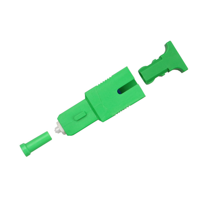
1260nm to 1625nm PON Service Signals - Pass, 1650nm OTDR Test Signal - Reflect, 1650nm OTDR FBG Reflectors

Contact me for free samples and coupons.
Whatsapp:0086 18588475571
Wechat: 0086 18588475571
Skype: sales10@aixton.com
If you have any concern, we provide 24-hour online help.
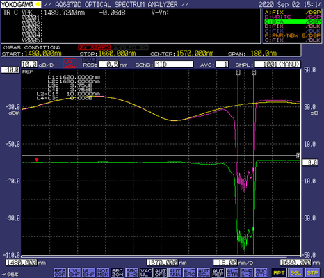
x| Product Name | 1650nm OTDR FBG Reflectors | Pass Band (nm) | 1260~1360&1460~1600&1600~1625 |
|---|---|---|---|
| Reflect Band (nm) | 1644.5~1655.5 | Insertion Loss (dB) | ≤1.0 |
| Return Loss (dB) | ≥35 | Polarization Dependent Loss (dB) | ≤0.4 |
| TDL (dB) | ≤0.5 | Ripple (dB) | ≤0.6 |
| Maximum Optical Power Handing (dBm) | 27 | Plug Times | 500 |
| Connector Type | SC/APC, SC/UPC, LC/APC, LC/UPC | Operating Temperature (℃) | -20 To +70 |
| Operation Humidity (%RH) | 5~93 |
Wavelength Division Multiplexers
1650nm OTDR FBG Reflectors
1260nm to 1625nm PON Service Signals - Pass
1650nm OTDR Test Signal - Reflect
![]()
*Operation Scheme-1650nm Reflector
Description
OTDR reflector is located at the Optical Network Unit (ONU) side of a Passive Optical Network (PON), which will reflect the test signal from the OTDR at the Optical Line Terminal (OLT) side, while the traffic signal of the PON system will pass through the reflector with very little loss. OTDR reflector is used to help to increase the sensitivity of the OTDR for checking the optical continuity of a subscriber, and troubleshooting (The reflector has a high reflection ratio and stable reflection, so the OTDR at the CO can obtain a stable peak, and it is possible to calculate the loss of an optical link on a PON network based on the reflection peak). The reflector can be installed at any responsible demarcation point to demarcate faults.
OTDR reflector is based on FBG technology to reflect the OTDR test signal. With wide bandwidth and low insertion loss, FBG reflectors are ideal to create high reflectance of their own intrinsic reflection wavelength at 1645~1655nm at the termination of a PON without disturbing traffic.
Features
* Fiber Bragg Grating (FBG) Technology
* Low insertion loss and reflectance at traffic wavelength
* High reflective power at a testing wavelength
* SC, LC, FC, or MU plug/jack, Pigtail types are optional, Easy to install
* Space-saving installation on patch panels and/or equipment interface
* Exceptional reliability and environmental stability
* Compatible with EPON, GEPON, GPON, 10G-PON, NG-PON2
* Bidirectional type is optional
Applications
* Smart ODN
* Create high reflectance at the termination of a PON without disturbing traffic
* Test reflectance from the central office
* Check optical continuity of a subscriber when adding them or troubleshooting
Specifications
| Item | Parameter | |||
| Wavelength Range(nm) | Pass Band | 1260~1360&1460~1600&1600~1625 | ||
| Reflect Band | 1644.5~1655.5 | |||
| Grade | P | U | ||
| Pass Band(dB) | IL | dB, @1260~1360 | ≤1.4 | ≤1.0 |
| dB, @1460~1600 | ≤1.4 | ≤1.0 | ||
| dB, @1600~1625 | ≤3.4 | ≤1.5 | ||
| ORL | dB, @1260~1360 | ≥35 | ≥35 | |
| dB, @1460~1580 | ≥35 | ≥35 | ||
| dB, @1580~1620 | ≥30 | ≥30 | ||
| dB, @1620~1625 | ≥20 | ≥22 | ||
| Reflect Band(dB) | ORL | dB, @1644.5~1655.5 | ≤1.0 | ≤1.0 |
| IL | dB, @1644.5~1655.5 | ≥21 | ≥21 | |
| PDL (dB) | ≤0.4 | |||
| TDL (dB) | ≤0.5 | |||
| Ripple (dB) | ≤0.6 | |||
| Maximum Optical Power Handing (dBm) | 27 | |||
| Plug Times | 500 | |||
| Connector Type | SC/APC, SC/UPC, LC/APC, LC/UPC | |||
| Operating Temperature (℃) | -20~+70 | |||
| Operation humidity (%RH) | 5~93 | |||
| Storage Temperature (℃) | -20~+70 | |||
| Operation humidity (%RH) | 5~93 | |||
*IL (dB) = -10Log10((Output Power/Input Power)
**ORL (dB) = -10Log10(Reflected Power/Input Power)
***To measure the Return Loss of the reflecting band, the light of 1650nm should be injected from the female side of the reflector and for the BiDi type, the light of 1650nm can be injected from both sides.
****Other specifications can be made on customer request
![]()
Package Dimension
![]()
Order Information
Connector Type, Grade,
Wavelength, Package Type, Directional
Example:
SC/APC, Grade P,
Pass-1260nm to 1625nm/Reflect-1650nm, Female to Male Adapter type, Unidirectional
OTDR FBG Reflectors
*Note: Customized Reflective Wavelength (1625nm, 1577nm, 155nm, etc.) and Package Type (Fast Connector type or Pigtail type) are Available.
ODN Planning Requirements
The length difference between two links must be greater than 1.5 times the split ratio of the second-level optical splitter on the shorter link. This ensures that the distance between any two reflectors is longer than 1.5 m so that reflection events on an OTDR test curve will not overlap.
![]()
*If L1 is less than L2, the difference between L1 and L2 must be greater than 1.5 x N1.
Application Scenario
* During project engineering, optical fiber carriers use a reflector and the Field Assistant to check the installation by phase, thereby implementing comprehensive ODN quality acceptance.
* CO engineers confirm acceptance results and create a data file of the optical fiber network project and maintain the file, which supports fast fault demarcation and location during a follow-up operation.
![]()
A: Output port on a first-level optical splitter
B: Output port on a second-level optical splitter
C: Drop Terminal port or ONU port
Main Flow of an ODN Acceptance Test
1. Deploy a feeder fiber and install a first-level optical splitter.
2. Install a reflector at point A and perform acceptance tests on the first-level optical splitter.
3. Remove the reflector at point A.
4. Deploy distribution fibers and install second-level optical splitters.
5. Install a reflector at point B and perform acceptance tests on the second-level optical splitter.
6. Remove the reflector at point B.
7. Deploy drop fibers and a Drop Terminal.
8. Install a reflector at point C and perform reflector loss tests.
9. (Optional) Retain the reflector at point C for follow-up line tests.
![]()


